Charging Relays
Some can also double as a parallel relay for starting engines from the house battery.
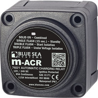
The Blue Seas m-Series Automatic Charging Relay is suitable for cross charging a house battery from an outboard engine that is connected to a start battery. Add a parallel battery switch for starting from a house battery.
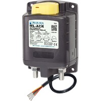
Blue Seas ML Series ACR's combine an ACR function and a parallel relay function capable of up to 500 amps on a continuous basis. They are available with or without a manual actuator.
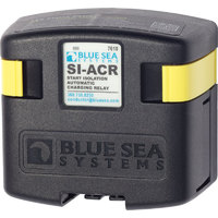
The SI-Series Automatic Charging Relay is rated for 12 and 24 volt systems up to 120 amps. They are not suitable for parallel starting.
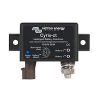
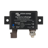
Victron Cyrix battery combiners include models for lead acid and Lithium Ion batteries. The higher current models can also be used for parallel starting operation.
In a boat with two battery banks, it is useful to be able to charge both banks while underway. Charge management devices connect two battery banks when charging, and isolate them from each other when not charging. If one battery becomes depleted, there will be a charged bank available for emergency starting.
There are two main types of charge management devices used on boats:
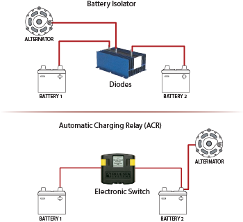 Automatic Charging Relays (or Voltage Sensitive Relays) use a relay combined with a circuit that senses when a charging source is being applied to either battery. When a charge is being applied, the ACR combines the batteries. When there is no charge present, the ACR isolates the batteries.
Battery Isolators are one-way electrical check valves that allow current to flow to, but not from, the battery. Special FET isolators have very low voltage drops and produce minimum heat. Older style diode isolators may have an excessive voltage drop making them unsutable for battery charging.
When choosing an ACR:
Current Management. ACRs can potentially be exposed to very high currents if the engine is cranked while the ACR has combined the batteries. This can occur when a charge source other than the alternator, such as a solar charger, has caused the ACR to close. Blue Sea Systems uses two methods to overcome this. ML- Series ACRs have high amperage contacts rated for engine starting, and the SI- Series ACR momentarily opens the relay, isolating the two batteries during starting.
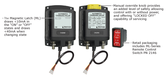
Remote Control. Blue Sea Systems ML- Series and SD-Series ACRs include a Remote Control Contura Switch so that ACR function can be controlled from a helm station or other convenient location.
Manual Override. In addition to the remote control switch, ML- Series ACRs are available with a local manual control knob to combine battery banks in an emergency.
Start Isolation. All Blue Sea Systems ACRs can be configured for Start Isolation, which provides temporary isolation of house loads from the engine circuit during engine cranking. This protects sensitive electronics from voltage sags and spikes in the starting circuit.
SI-Series ACR
120 amp SI-Series ACR automatically manages the charging of two battery banks and
isolates batteries during starting to protect sensitive electronics.
Combined wit a Dual Circuit Plus battery switch, an effective and low cost means of implementing a dual battery system is created.
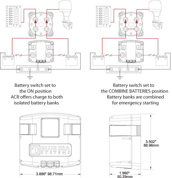
ML-Series ACR
500 Ampere Bi-Stable Magnetic Latching Automatic Charging Relay automatically manages the charging of two large battery banks and offers optional manual override for emergency battery paralleling.
Features:
- Automatically manages the charging of two large battery banks
- Allows paralleling of battery banks for emergency starting
- 500 Ampere continuous rating to support high-output alternators
- Magnetic Latch (ML)—ACR draws very low current (<40mA to monitor terminal voltage) in the "ON" or "OFF" states, and draws moderate current for very short time when changing state
- Dual sensing—senses charge on both battery banks
- Start Isolation (SI)—can be configured for temporary isolation of House loads from Engine circuit during engine cranking to protect sensitive electronics
- Engine Isolation (EI)—can be configured for isolation of two engines while both are running to protect engine electronics and maximize alternator output
- Senses charging on two battery banks
- LED output to remotely indicate when batteries are combined, isolated, in voltage lockout, or in Start or Engine isolation
- 3/8"-16 tin-plated copper studs for maximum conductivity and corrosion resistance
- 7/8" (22mm) stud length accepts multiple cable terminals
- Silver alloy contacts provide high reliability for switching live loads
- Label recesses for circuit identification
Argo Diode Battery Isolators
Diode battery isolators allow simultaneous charging of two or more batteries from one alternator, without connecting the batteries together. Discharging the accessory battery for example will not result in also discharging the starter battery.
The Argo battery isolators feature a low voltage drop thanks to the use of Schottky diodes: at low current the voltage drop is approximately 0.3V and at the rated output approximately 0.45V. All models are fitted with a compensation diode that can be used to slightly increase the output voltage of the alternator. This compensates for the voltage drop over the diodes in the isolator.
Argo FET Battery Isolators
Similarly to diode battery isolators, FET isolators allow simultaneous charging of two or more batteries from one alternator (or a single output battery charger), without connecting the batteries together.
In contrast with diode battery isolators, FET isolators have virtually no voltage loss. Voltage drop is less than 0.02V at low current and averages 0.1V at higher currents.
When using ARGO FET Battery Isolators, there is no need to also increase the output voltage of the alternator. Care should taken however to keep cable lengths short and of sufficient cross section.
Alternator energize input
Some alternators need DC voltage on the B+ output to start charging. Obviously, DC will be present when the alternator is directly connected to a battery. Inserting a Diode or FET splitter will however prevent any return voltage/current from the batteries to the B+, and the alternator will not start. The new Argo diode and FET isolators have a special current limited energize input that will power the B+ when the engine run/stop switch is closed.