Basic On-Chassis Electrical System
Your vehicle electrical system can only be as good as the electrical system design and the quality of the components employed. In particular, the proper design and implementation of the heavy DC power equipment are often not understood.
Charging an on-chassis system is particularly simple as the wiring lengths from the engine start battery to the house battery are relatively short. This means that a simple relay-based system can charge the house battery without a significant voltage drop. The same relay can supply power to a trailer DC connector if required. For vehicles with "smart" engine charging, a DC-DC charger may be required to boost the charging voltage at the battery.
Solar panels can also charge the house battery in addition to the engine charging when underway. Systems with a generous solar panel allowance may get by with solar panel charging alone.
The vehicle chassis is used for the main system negative (earth) connection. Note that the vehicle chassis is connected to the negative busbar side of the battery monitor shunt.
Heavy DC wiring should be of significant size, well organised, and all circuits must be protected from an overload situation to avoid fire risk. The battery switch is an essential component that can isolate the electrical system from the battery if there is a fire or other risk. Fuses protect each of the circuits that provide power to the system components. A battery monitor allows proper charge management of the battery.
DCDM2 On-Chassis System Electrical Schematic
DC Distribution Board
The DCD board works as the wiring hub of all the heavy DC circuits. It provides mounting points for all cables, a battery switch, a fused busbar system, a ground busbar and a mounting location for the Victron BMV battery monitor shunt. Other brand shunts can also be accommodated offboard.
The circuit above illustrates a design that incorporates the DCD board into a full on-chassis electrical system.
Although this system might be considered overkill for simple low power systems, it comes into its own for vehicles using inverters or inverter chargers over 500-watts power rating. With a 300-amp combined current handling capacity, inverter chargers up to 3,000VA for12-volt systems or 5,000VA for 24-volt systems are well catered for.
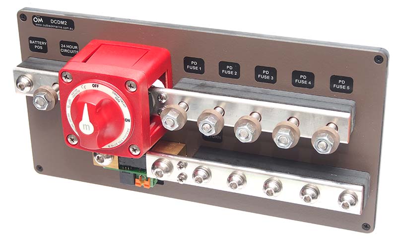
DCDM2 DC Distribution Board
House Battery System
The house battery can be made up of a number of AGM Deep Cycle Batteries. A lithium battery may also be used. When a self-contained lithium battery with inbuilt BMS is employed, be careful that the battery charge and discharge characteristics are compatible with the charge sources and loads - especially the inverter charger. A good choice of this style of battery is the Enerdrive B-Tec Lithium Battery. The 200AH model at the link is suitable for inverter chargers up to 2,000 VA.
When using larger lithium batteries such as the Victron Smart Lithium Batteries, additional components for the external BMS are required. This setup will be shown in a separate application note.
The battery positive terminal connects to a battery switch mounted on the DCD board and the negative connects to the battery monitor shunt (which measures net current in and out of the house battery). A negative power distribution busbar on the load side provides a connection point for the negative wire of all load circuits and the vehicle chassis.
Battery Monitor
Understanding the battery state of charge (SOC) is essential for good battery management. For this, we use a BMV-712 Battery Monitor which includes a Bluetooth interface to use with the free Victron Connect smartphone App. The DCD board has a location for mounting the battery monitor shunt. Note that only one side of the shunt connects to the battery negative terminal.
Inverter Charger
The inverter charger will provide AC power when the vehicle is away from the grid power. when plugged into the grid, it will be the battery charger. The size of the inverter charger depends primarily on the simultaneous power draw of any AC appliances. For example, a system capable of powering an electric kettle (2,200-watts) would use a Victron Multiplus 12/3000 product. The size of the inverter charger will also dictate the house battery capacity.
The Inverter charger DC power is sourced from a Terminal Fuse mounted on the positive busbar of the DCD board and the ground return connects to the negative busbar. The recommended fuse size will be determined by the inverter charger being used. Best practice will provide an Isolation Switch in the positive lead near the inverter charger if it is not located in the immediate vicinity of the main battery switch on the DCD board.
House Circuit Breaker Panel
Circuit breakers on this panel feed power to most DC consumer devices. When the main battery switch is turned off, power is removed from all circuits connected to it. House panel power is sourced from a fuse on the positive busbar.
Essential circuits are those that require power on a 24-hour a day basis irrespective of the main battery switch being turned on or off. To realise this, a section of the house panel can be powered directly from the battery via a fuse mounted on the battery side of the battery switch.
Solar power can also be considered an essential circuit so that solar battery charging can continue when the main battery switch is turned off. A master essential circuit breaker must be used to provide full battery isolation in case of an emergency.
Solar Panels
A Solar Panel Controller is connected to the essential circuit system via a circuit breaker on the house panel. To meet electrical standards, a two-pole isolator is required between the solar panels and the controller. The controller should be mounted close to the DCD board.
An alternative arrangement is to connect the solar controller to the main power bus that is controlled by the battery switch. However, in this case, the battery switch would need to be left on for solar charging.
Vehicle Connection - DC to DC Charger
The vehicle alternator is used for charging the house battery. As the relative cable length between the engine and house battery is relatively short, a direct connection can be made with a minimal voltage drop when a larger cable size is used. A 285 Series Circuit Breaker is used for the connection to the vehicle starter battery and a relay that is energised by the ignition circuit allows power to pass when the engine is running. The vehicle chassis earth can be used for the negative power connection.
An Andersen Connector at the tow bar provides power to a trailer if used. Be sure to use a healthy cable size for the positive lead between the tow bar area and the engine start battery.
For vehicles that use a "smart" alternator, a DC-DC charger may be beneficial. The Victron Orion-Tr 12/12-18A is a good example. It has an adjustable output voltage that is suitable for AGM or lithium batteries and has a control input for the ignition circuit.
Example System
A parts list for an example system is listed below. Contact Outback marine for further guidance. We also offer a full schematic and consulting service at a time and materials rate if you require detail guidance.
| Item | Qty | 1200 VA System |
|---|---|---|
| House Battery Bank (340-AH) | 2 | Victron 12V/170Ah AGM Super Cycle Battery |
| Battery Monitor | 1 | Victron Battery Monitor BMV-712 with Bluetooth |
| DC Distribution Board | 1 | DCDM2 DC Distribution Board |
| Inverter | 1 | Victron Phoenix 1,600 VA Smart Inverter |
| Inverter Isolator | 1 | Blue Sea Switch Battery M ON/OFF w/Knob |
| Inverter Fuse (200-amp) | 1 | Blue Sea Fuse Terminal 200-amp |
| Battery Charger | 1 | Victron Phoenix IP43 Smart Charger (30-amp) |
| Battery Charger Fuse (50-amp) | 1 | Blue Sea Terminal Fuse 50-amp |
| House Circuit Breaker Panel | 1 | Custom to order |
| House Panel Fuse (50-amp) | 1 | Blue Sea Fuse Terminal 50A |
| Solar Panels | 1 | Trina 275-watt Panel |
| Solar Panel Controller | 1 | Victron SmartSolar MPPT 75/15 |
| Solar Panel Isolator | 1 | 16A 350V DC Circuit Breaker (2 poles) |
| Essential Circuits Fuse | 1 | Blue Sea Fuse Terminal 50A |
| Engine Circuit Breaker | 1 | 285 Series Circuit Breaker |
| Engine Relay | 1 | Automotive Relay |
| DC to DC Charger | 1 | Victron Orion-TR 12/12-18A |
| DC-DC Charger Fuse | 1 | Blue Sea Fuse Terminal 50A |
On-chassis electrical system design suitable for 4WD and Canopy Applications
- Rugged busbar based system with terminal fuses
- 300 amp current rating
- Optional DC-DC charging or direct relay charging